WAGO Compact Controller 100
The WAGO Compact Controller 100 (CC100) is a compact DIN rail-mounted industrial controller powered by a dual-core ARM Cortex-A7 processor running real-time Linux. It combines integrated digital and analog I/O points on a single device, making it ideal for compact machines, building automation, and distributed sub-systems.
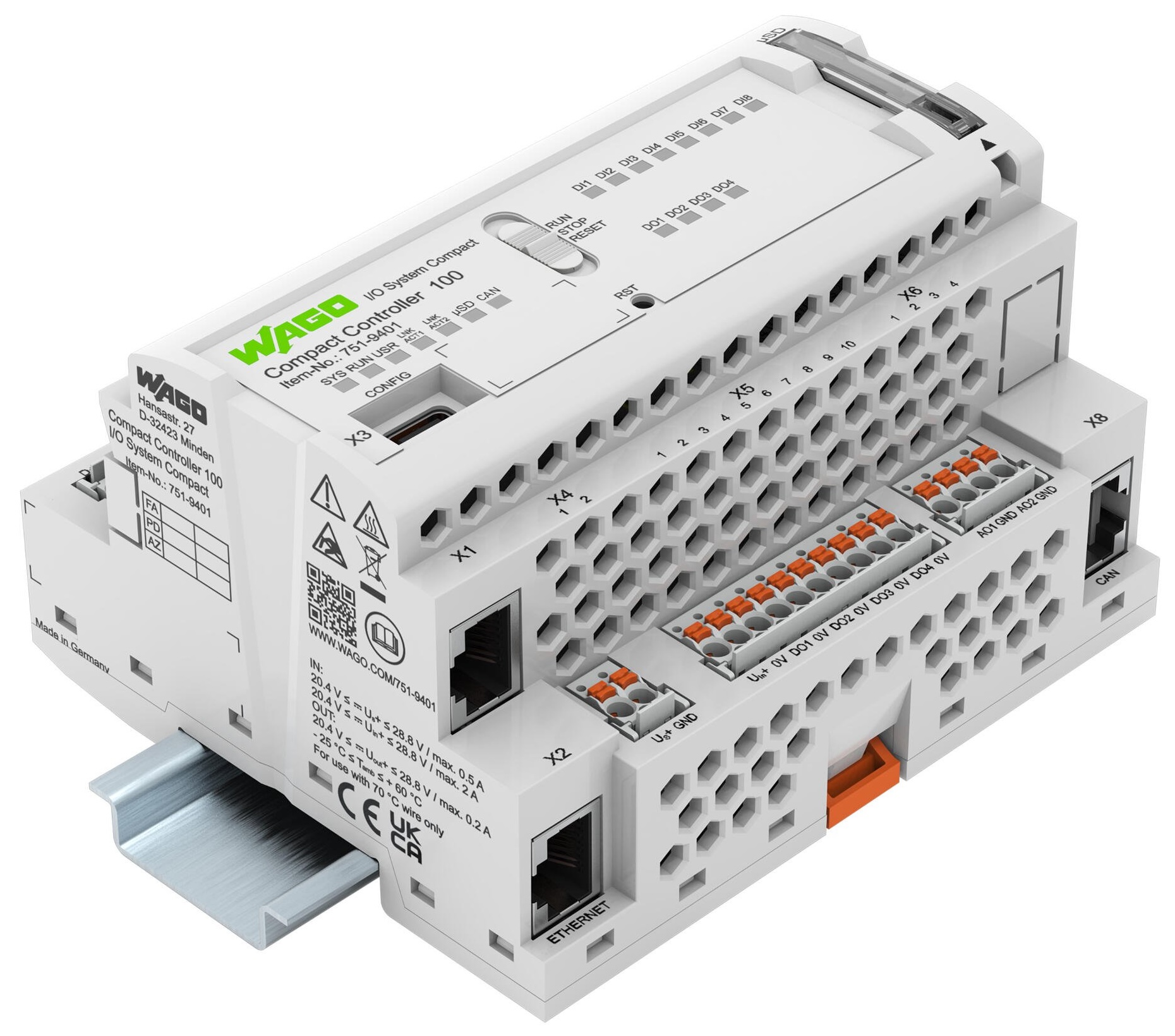
Adapnex provides native hardware support for the CC100 through the CC100IODriver class. The driver communicates directly with the onboard peripheral hardware through real-time kernel subsystems, providing deterministic cycle times down to single-millisecond periods.
Hardware Interfaces
The CC100 features a fixed set of onboard digital and analog terminals. The table below lists all available channels and their driver interface mappings:
| Terminal | Signal | Electrical Specification | Data Type |
|---|---|---|---|
|
Digital Inputs |
24 V DC (IEC 61131-2) |
|
|
Digital Outputs |
24 V DC, 0.5 A high-side |
|
|
Analog Inputs |
0 to 10 V DC, 12-bit |
|
|
RTD Inputs |
PT1000 / NI1000, 450 to 4400 Ohm |
|
|
Analog Outputs |
0 to 10 V DC, 12-bit |
|
All input channels support continuous input binding with >>, and all output channels support continuous output binding with <<. Alternatively, values can be accessed directly using the value() accessor.
Driver Setup and Initialization
To use the onboard I/O, instantiate the CC100IODriver within a cyclic task group during the application setup() routine:
#include "adapnex.h"

void setup() {
    // Create a 20ms cyclic task group
    const auto control_group = Application::CreateCyclicTaskGroup({.period = 20ms});

    // 1. Register the hardware driver
    const auto io_driver = control_group->CreateTask<CC100IODriver>();

    // 2. Register application tasks
    const auto main_task = control_group->CreateTask<MainTask>();

    // 3. Connect hardware channels to task variables
    io_driver->DI1 >> main_task->start_button;
    io_driver->DO1 << main_task->run_lamp;
}
Reading Digital and Analog Inputs
Digital inputs evaluate to true when a 24 V signal is applied to the corresponding terminal. Mappings automatically propagate changes each cycle during the pre-update phase.
Analog voltage inputs (AI1 and AI2) deliver pre-scaled floating point values in volts, ranging from 0.0f to 10.0f.
Resistance inputs (PT1 and PT2) return the measured resistance in ohms across the range of 450 to 4400 Ohm. For a standard PT1000 platinum RTD sensor with a nominal resistance of 1000 Ohm at 0 °C, a linear approximation with a temperature coefficient of 3.85 Ohm/°C provides a simple conversion. Because the resistance-temperature relationship is slightly non-linear, wide temperature ranges benefit from polynomial approximations or the Callendar-Van Dusen equation:
float resistance_ohms = 1000.0f;
float temperature_celsius = 0.0f;

void Update() override {
    // Linear approximation around room temperature
    temperature_celsius = (resistance_ohms - 1000.0f) / 3.85f;
}
Driving Digital and Analog Outputs
Digital outputs (DO1 through DO4) provide 24 V DC high-side power to connected relays, solenoids, or indicator lights. Connecting a boolean task member to an output channel via << routes the calculated state to the hardware during each post-update phase.
Analog outputs (AO1 and AO2) accept floating-point setpoints between 0.0f and 10.0f volts. Setpoint values outside this range are clamped to the electrical limits of the output stage.
Desktop Simulation
Adapnex includes a desktop simulator target for the CC100 (wago_cc100_simulator). The simulator reproduces the complete CC100IODriver programming interface on your development workstation without requiring access to physical hardware.
When running against the simulator target, Adapnex launches a graphical desktop window displaying the controller faceplate. You can toggle digital input switches, adjust analog potentiometers, and observe digital output LEDs and analog output plots in real time.
Because the simulator provides the identical public interface as the physical driver, you can develop and verify control logic on your PC and deploy the identical code to physical hardware by switching the build target:
-
Physical hardware target:
wago_cc100(cross-compiles for a WAGO CC100 device) -
Workstation simulator target:
wago_cc100_simulator(compiles natively on host)
Full Example: Climate and Exhaust Control
The following complete application demonstrates reading a PT1000 temperature sensor on PT1 and a duct pressure sensor on AI1. The controller turns on a status lamp on DO1 and regulates a variable-speed exhaust fan on AO1:
#include "adapnex.h"

class VentilationController final : public Task {
public:
    // Inputs mapped from hardware
    float rtd_resistance = 1000.0f;
    float duct_pressure_volts = 0.0f;
    bool enable_switch = false;

    // Outputs mapped to hardware
    bool run_indicator = false;
    float fan_speed_volts = 0.0f;

    void Update() override {
        if (!enable_switch) {
            run_indicator = false;
            fan_speed_volts = 0.0f;
            return;
        }

        run_indicator = true;

        // Calculate temperature from PT1000 sensor
        const float temp_c = (rtd_resistance - 1000.0f) / 3.85f;

        // Modulate fan speed based on ambient temperature
        if (temp_c > 35.0f) {
            fan_speed_volts = 10.0f;
        } else if (temp_c > 25.0f) {
            fan_speed_volts = 2.0f + (temp_c - 25.0f) * 0.8f;
        } else {
            fan_speed_volts = 2.0f;
        }
    }
};

void setup() {
    const auto group = Application::CreateCyclicTaskGroup({.period = 50ms});

    // Register driver and controller tasks
    const auto io_driver = group->CreateTask<CC100IODriver>();
    const auto controller = group->CreateTask<VentilationController>();

    // Map digital and analog inputs
    io_driver->DI1 >> controller->enable_switch;
    io_driver->PT1 >> controller->rtd_resistance;
    io_driver->AI1 >> controller->duct_pressure_volts;

    // Map outputs to physical terminals
    io_driver->DO1 << controller->run_indicator;
    io_driver->AO1 << controller->fan_speed_volts;
}