Getting Started with Adapnex
Welcome to Adapnex!
If you are coming from the world of Industrial Automation, you likely know the pain of proprietary "walled gardens": specialized IDEs, licensing dongles, and the struggle to use modern version control like Git.
If you are coming from the world of Software Engineering, you might be wondering why controlling a machine isn’t as simple as writing a C++ program and hitting "Run."
Adapnex bridges this gap. It is a streamlined C++ SDK that runs on Real-Time Linux, allowing you to build deterministic industrial control applications easily using the tools you already know and love: VS Code, CMake, Git, and CI/CD.
Installing Adapnex
To get started, install the Adapnex VS Code Extension or CLI for your platform:
-
VS Code Extension
-
CLI (macOS/Linux)
-
CLI (Windows)
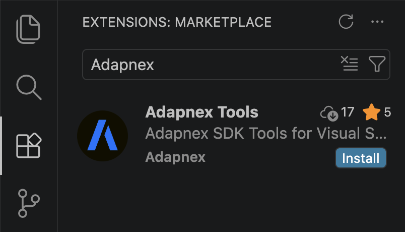
Search for "Adapnex" in the VS Code Extensions Marketplace and click Install:
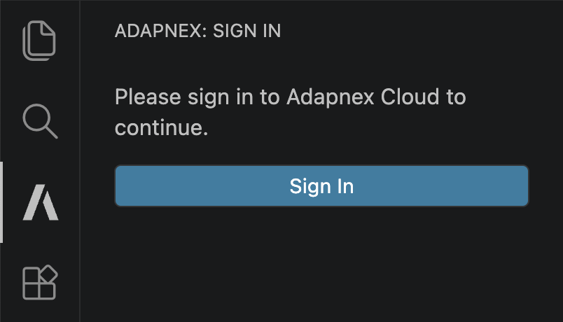
Once you’ve installed the VS Code Extension, sign in to continue:
By installing Adapnex software, you agree to our Terms & Conditions.
Run the following command in your terminal:
curl -fsSL https://download.adapnex.com/install.sh | bashOnce you’ve installed the CLI, log in to continue:
adapnex loginBy installing Adapnex software, you agree to our Terms & Conditions.
Run the following command in PowerShell:
irm https://download.adapnex.com/install.ps1 | iexOnce you’ve installed the CLI, log in to continue:
adapnex loginBy installing Adapnex software, you agree to our Terms & Conditions.
What We Are Building
We are going to build an Interactive Square Wave Generator as a toy example to demonstrate the core concepts of Adapnex. The application will blink an LED at a variable frequency based on an analog input voltage.
Input: A Switch to enable the generator and an Analog Potentiometer (0-10V) to control the frequency.
Output: An LED that blinks at the calculated rate.
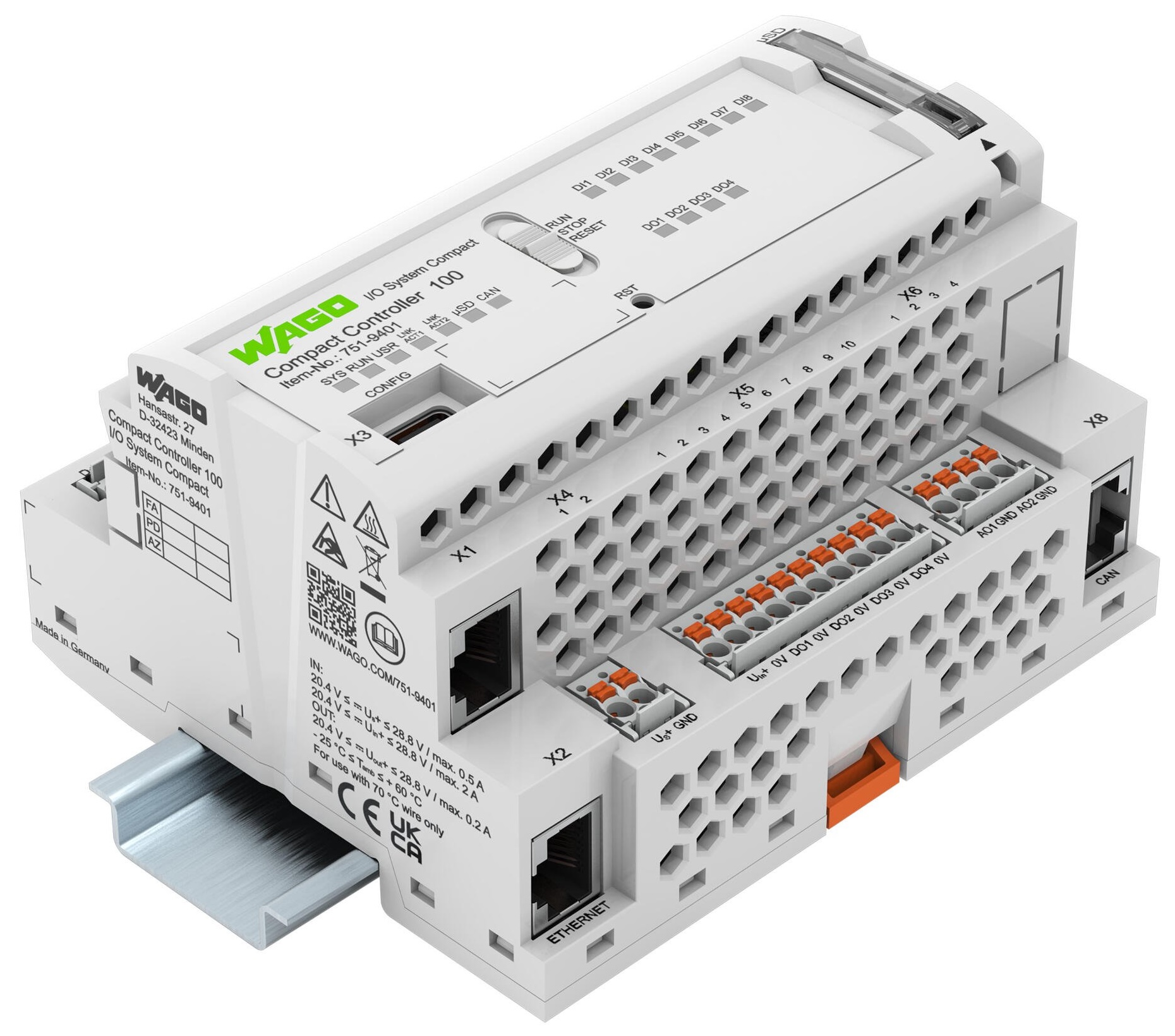
This guide we will use the WAGO Compact Controller 100 (CC100), a good entry point for Industrial Software Engineering with a range of built-in digital and analog I/Os in a compact footprint. However, as Adapnex is hardware-agnostic, the same code will work on any other supported platform with minor adjustments to account for different pinouts.
|
Don’t have any hardware?
No problem. We will use the Adapnex Simulator to build, wire, and test this entire application visually on your PC before we touch any real hardware. |
1. Defining the Control Logic
In Adapnex, control logic is encapsulated in Tasks.
A Task is simply a C++ class that holds your variables (state) and your code (logic).
Crucially, this task doesn’t know about the hardware. It operates on pure software variables, which makes it easy to test, reuse, and simulate.
Create a new directory for your project and add a header file named main_task.h with the following content:
#pragma once

#include "adapnex.h"

class MainTask final : public Task {
public:
    // --- Interface Variables ---
    // These are simple C++ types, effectively our "Software IO".

    // Inputs
    bool switch_in = false;         // Digital input from switch
    float analog_voltage_in = 0.0f; // Analog input from potentiometer (0-10V)

    // Outputs
    bool blink_out = false;  // Digital output for LED state
    float analog_out = 0.0f; // For the visualization in the simulator

private:
    // --- Function Blocks ---
    // Instantiate a standard Square Wave Generator.
    // This block maintains its own internal timer state.
    SquareWaveGenerator generator;

    // --- The Control Loop ---
    // This function runs cyclically (e.g., every 20ms).
    void Update() override {
        // 1. Process Logic
        // Convert voltage to duration:
        // 0V -> 0ms (Fastest)
        // 10V -> 500ms (Slowest)
        const Duration t = static_cast<int>(analog_voltage_in * 50) * 1ms;

        // 2. Execute Generator
        // If 'switch_in' is true, toggle 'blink_out' with ON/OFF time 't'.
        generator(switch_in, t, t, blink_out);

        // 3. Map Output
        // For visualization, output 10V when blink_out is true, 0V otherwise.
        analog_out = blink_out ? 10.0f : 0.0f;
    }
};|
Key Takeaway
This looks like standard C++ because it is standard C++.
However, the |
2. Connecting Physical I/O
Next, we need to map our software variables to the physical pins of the controller.
We perform this configuration in main.cpp.
This file acts as the "Software Wiring Diagram."
Whether we are running on the real WAGO CC100 or the Simulator, this code remains exactly the same. The simulator is API-compatible with the physical driver, allowing it to intercept these signals and display them on your screen.
Add a new file named main.cpp to your project directory:
#include "adapnex.h"

#include "main_task.h"

// The 'setup' function is the entry point for Adapnex applications
void setup() {
    // --- 1. Configure the Scheduler ---
    // Create a Cyclic Task Group that runs every 20ms.
    const auto main_group = Application::CreateCyclicTaskGroup(20ms, 0);

    // Instantiate our control logic task
    const auto main_task = main_group->CreateTask<MainTask>();

    // --- 2. Configure Hardware Drivers ---
    // Add the driver for the WAGO Compact Controller 100.
    const auto io_driver = main_group->CreateTask<CC100IODriver>();

    // --- 3. Wiring ---
    // The '>>' and '<<' operators represent physical signal flow.

    // Connect Inputs: Driver >> Task
    io_driver->DI1 >> main_task->switch_in;         // Map DI1 to 'switch_in'
    io_driver->AI1 >> main_task->analog_voltage_in; // Map AI1 to 'analog_voltage_in'

    // Connect Outputs: Driver << Task
    io_driver->DO1 << main_task->blink_out;  // Map 'blink_out' to DO1
    io_driver->AO1 << main_task->analog_out; // Map 'analog_out' to AO1
}|
Why this matters
Notice how clean the separation between logic ( |
3. Build Configuration
Adapnex projects use CMake, the industry standard for C++ build automation. This ensures your project is portable and works with any major IDE (VS Code, CLion, Visual Studio, etc.)
Add a CMakeLists.txt file to your project directory with the following content:
cmake_minimum_required(VERSION 3.29)
project(example_blink)

# Create the executable application
# 'adapnex_executable' handles toolchains and dependencies automatically.
adapnex_executable(example_blink main.cpp)|
Key Takeaway
You don’t need to manually configure complex compiler flags for cross-compilation and Real-Time Linux.
The |
4. Interactive Simulation
Now for the fun part. Before we commit to real hardware, let’s verify our wiring and logic visually. Adapnex provides a Desktop Simulator for the WAGO CC100. This builds a native executable for your PC that launches a graphical interface representing the device.
-
Build and run the simulator:
-
VS Code
-
CLI
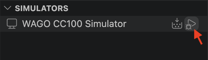
In the Adapnex Extension sidebar, click on the Run icon next to the WAGO CC100 Simulator target. This will build the simulator and launch the interface.
Run the Adapnex CLI build command for the
wago_cc100_simulatortarget.adapnex build wago_cc100_simulator example_blinkThe Adapnex CLI will output the path to the generated binary. Run it to launch the interface.
-
-
Interact! You will see the WAGO CC100 faceplate.
-
Toggle
DI1to simulate the switch. You should see theDO1LED start flashing. -
Drag the slider for
AI1to change the voltage. Notice the blink frequency changing in real-time. -
Observe the graph at the bottom. It visualizes
AO1, showing the square wave we generated.
-
5. Verification: Unit Testing
The simulator is excellent for "feeling" the application, but for robust engineering, we need automated tests. Because Adapnex is native C++, we can use standard testing frameworks like Google Test to prove our logic is correct and catch regressions instantly in our CI/CD pipelines.
The Adapnex Simulation fixture allows you to "fast-forward" time, running your real-time logic instantly on your PC.
Add a file named main_test.cpp in your project directory with the following content:
#include "adapnex.h"

#include <gtest/gtest.h>

#include "main_task.h"

// Test Case 1: Verify logic with low voltage (Fast Blink)
TEST_F(Simulation, MainTaskFastBlink) {
    // Setup a virtual scheduler
    const auto main_group = Application::CreateCyclicTaskGroup(10ms, 0);
    const auto main_task = main_group->CreateTask<MainTask>();

    // 1. Simulate Inputs
    main_task->switch_in = true;
    main_task->analog_voltage_in = 2; // 2V -> 100ms duration (Period 200ms)

    // 2. Advance time and check state
    for (int i = 0; i < 10; ++i) {
        Simulate(100ms);
        ASSERT_TRUE(main_task->blink_out); // Should be ON
        Simulate(100ms);
        ASSERT_FALSE(main_task->blink_out); // Should be OFF
    }
}

// Test Case 2: Verify logic with high voltage (Slow Blink)
TEST_F(Simulation, MainTaskSlowBlink) {
    const auto main_group = Application::CreateCyclicTaskGroup(10ms, 0);
    const auto main_task = main_group->CreateTask<MainTask>();

    main_task->switch_in = true;
    main_task->analog_voltage_in = 5; // 5V -> 250ms duration (Period 500ms)

    for (int i = 0; i < 10; ++i) {
        Simulate(250ms);
        ASSERT_TRUE(main_task->blink_out);
        Simulate(250ms);
        ASSERT_FALSE(main_task->blink_out);
    }
}
Now we need to tell the buildsystem (CMake) about our new tests.
Append the following lines to your CMakeLists.txt:
# Enable unit testing for this project
enable_testing()

# Register the test suite
# This sets up the target for running automated unit tests.
adapnex_tests(example_blink_tests main_test.cpp)
To run these tests, you can use either the VS Code Extension or the CLI.
-
VS Code
-
CLI
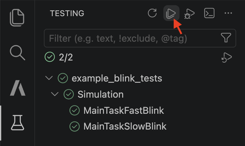
The Testing sidebar in VS Code should automatically detect all test suites defined in your project. You may need to click the refresh button to see the new tests. Click the Run Tests icon to execute them.
The CLI test command automatically builds and runs all test suites defined in your project.
adapnex test|
Key Takeaway
You just verified your real-time control logic without waiting for hardware delivery, wiring a cabinet, or risking a machine crash. |
6. Build and Deploy
We have verified our logic in unit tests and validated our system integration in the simulator. We are now ready to deploy to real hardware.
-
Wire the WAGO CC100 according to the following schematic:

-
Build and run the application on the device:
-
VS Code
-
CLI
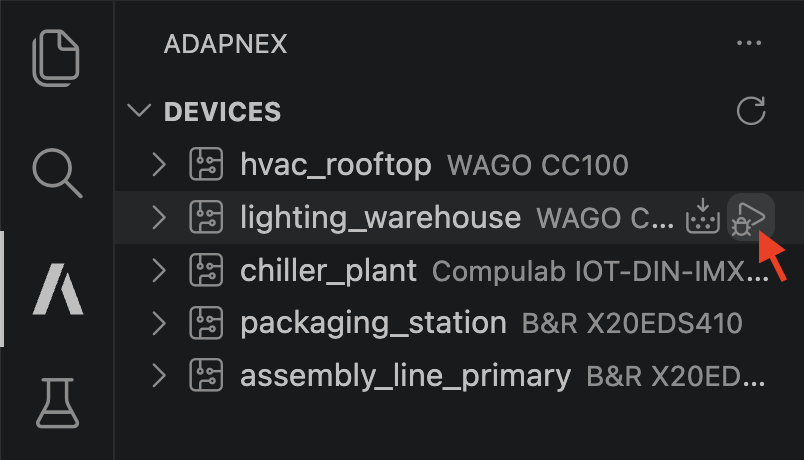
In the Adapnex Extension sidebar, choose a device to run the application on and click the Run icon next to it.
Use the CLI app run command to deploy the compiled binary to your device (replace
test_benchwith the name of your device).adapnex app run test_bench example_blink -
Conclusion: The Future of Your Control Systems
Congratulations! You have just built a real-time industrial control application. But unlike traditional approaches, you have achieved several significant milestones:
-
Hardware Independence: You verified the logic with
main_test.cppbefore configuring a single driver. -
Virtual Commissioning: You verified the wiring and behavior using the interactive Simulator.
-
Modern Workflow: You did industrial control programming on a standard IDE that naturally comes with Git version control, refactoring tools, and AI assistants.
-
Clean Implementation: You used the power of Real-Time Linux without the complexity of system calls.
Next Steps
From here, the sky is the limit. Because you are in C++, you can easily integrate:
-
Advanced Control: Use existing C++ libraries for PID control, Motion Planning, or Signal Processing.
-
IoT & Cloud: Send telemetry instantly to Adapnex Cloud with just a few lines of code, making it accessible & readily available for Grafana, Superset, Plotly, OpenMCT, Zarr formats, and your favorite observability stacks and data pipelines.
-
CI/CD: Set up a GitHub Action to run your simulation tests automatically on every commit.
Welcome to the new era of Industrial Software Engineering.