B&R X20 System
The B&R X20 system is a modular slice I/O platform designed for demanding industrial automation environments. Unlike fixed-I/O hardware, modular systems allow machine builders to assemble custom combinations of digital inputs, digital outputs, analog channels, temperature sensors, counters, and communication slices on a shared backplane.
In Adapnex, the B&R X20 hardware tree is defined directly in C++ during the application setup() routine. Control logic remains decoupled from the physical bus topology, allowing tasks to operate on generic variables while drivers manage the underlying bus communication.
Bus Controller Architecture
Communication with the physical slice modules is managed by the X20BC0087Driver. The X20BC0087 bus controller connects to the host machine over Ethernet and bridges process image data to the high-speed X2X Link backplane.
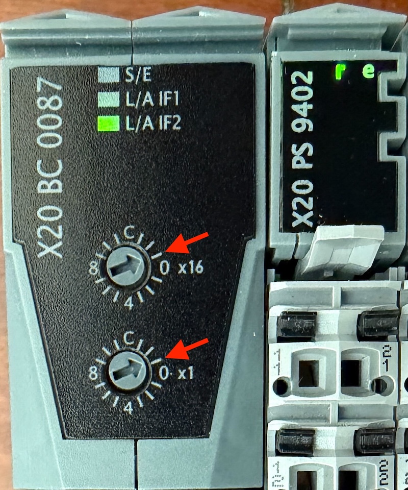
Network Setup and Rotary Switches
The bus controller features two decimal rotary switches labeled x10 and x1 that determine its station address:
-
Default Address (
0xFF): When the rotary switches are set to0xFF, the bus controller loads standard factory defaults. The controller assigns itself the static IP address192.168.100.1and runs the X2X Link backplane at a4mscycle time. -
Custom Addresses (
0x00to0xF0): Setting an address in this range allows you to pass custom IP addresses and shorter bus cycle times down to500us. -
Factory Reset (
0xFE): Forces a hard reset to factory defaults and ignores external configuration commands.
To communicate with a bus controller at the default address (0xFF), configure your host device network adapter with a static IP address on the same subnet, such as 192.168.100.10 with subnet mask 255.255.255.0.
When using custom switch positions (0x00 to 0xF0), pass the matching IP address and cycle time to the driver constructor:
// Configure custom IP address and 500us backplane cycle time
const auto io_driver = group->CreateTask<X20BC0087Driver>(
    std::array<uint8_t, 4>{192, 168, 100, 5},
    500us
);
Lifecycle and Teardown Safety
During application shutdown, the driver sends the final output process image across the X2X Link so that fallback values written during teardown remain asserted on physical actuators, as detailed in the Application Lifecycle guide.
Adding Modules
Modules are declared in C++ using the AddModule() method on the bus controller instance:
The driver resolves module bindings according to two principles:
-
Partial Topologies: Your code only needs to declare the modules required by your control logic. Any physically installed modules that are not added in code are ignored by the driver and consume no process image overhead.
-
Relative Ordering by Type: Modules are bound sequentially by type. The first call to
AddModule()for a module type claims the first physical module of that type found from left to right along the rail. The second call claims the next physical module of that same type.
Constructor arguments passed to AddModule() forward directly to the module class. For example, configure the sensor type and filter duration on a thermocouple module during registration:
// Configure thermocouple slice for Type J sensors with 16ms filter time
const auto temp_sensor = io_driver->AddModule<X20AT6402>(
    X20AT6402::SensorType::kTypeJ,
    16ms
);
Dynamic and Optional Configurations
Defining hardware topologies in native C++ code provides flexibility that static configuration files or graphical tools cannot match. Because AddModule() runs during setup(), you can execute standard C++ control flow to adapt your hardware footprint.
Programmatic Configuration
Your application can parse a recipe file, query environment settings, inspect physical DIP switches, or react to runtime discovery before deciding which modules to register:
Detecting Optional Backplane Modules
In modular machinery, optional machine stations or tooling heads may only be physically installed on specific customer variants. When code attempts to register a module type that is not physically detected on the backplane, AddModule() throws a ModuleNotFoundException.
You can catch this exception during setup() to detect whether an optional slice is present. Placing the module instantiation and signal mapping directly inside a try block allows a single compiled binary to service multiple physical machine configurations safely:
#include "adapnex.h"

void setup() {
    const auto group = Application::CreateCyclicTaskGroup({.period = 10ms});

    // 1. Initialize bus controller and base machine I/O
    const auto io_driver = group->CreateTask<X20BC0087Driver>();
    const auto base_do = io_driver->AddModule<X20DO8322>();
    const auto main_task = group->CreateTask<MainTask>();
    base_do->DO1 << main_task->core_running;

    // 2. Optional tooling module: register and map if physically present
    try {
        const auto optional_temp = io_driver->AddModule<X20AT6402>();
        optional_temp->TC1 >> main_task->tool_temperature;
    } catch (const ModuleNotFoundException &) {
        // Module not fitted on this machine build
    }
}
Module Catalog
|
The library of supported B&R X20 modules is continuously expanding. Support for additional slice modules can be added upon request. |
Adapnex includes pre-configured driver classes for a broad selection of B&R X20 slice modules:
Digital Inputs
-
X20DI0471: 4 digital inputs, 24 V DC, sink or source. -
X20DI4653: 4 digital inputs, 24 V DC, 1-wire connection. -
X20DI6553: 6 digital inputs, 24 V DC, 1-wire connection. -
X20DI8371: 8 digital inputs, 24 V DC, sink or source. -
X20DI9371: 12 digital inputs, 24 V DC, sink or source. -
X20DI9372: 12 digital inputs, 24 V DC, 2-wire connection.
Digital Outputs
-
X20DO2649: 2 digital outputs, 24 V DC, 2.0 A high-side switching. -
X20DO4649: 4 digital outputs, 24 V DC, 2.0 A high-side switching. -
X20DO6639: 6 digital outputs, 24 V DC, 0.5 A high-side switching. -
X20DO8322: 8 digital outputs, 24 V DC, 0.5 A high-side switching. -
X20DO9322: 12 digital outputs, 24 V DC, 0.5 A high-side switching.
Analog Outputs
-
X20AO2622: 2 analog outputs, +/-10 V or 0 to 20 mA, 12-bit. -
X20AO2632: 2 analog outputs, +/-10 V or 0 to 20 mA, 16-bit. -
X20AO4622: 4 analog outputs, +/-10 V or 0 to 20 mA, 12-bit. -
X20AO4632: 4 analog outputs, +/-10 V or 0 to 20 mA, 16-bit. -
X20AO4635: 4 analog outputs, 0 to 10 V or 4 to 20 mA, 16-bit.
Specialized Modules
-
X20DC1196: 1-channel high-speed incremental encoder and counter module, with 32-bit counter registers, latch inputs, and configurable AB counter modes. -
X20DS4389: Digital signal processing module with configurable counter and measurement channels. -
X20PS9402: Power supply module with integrated bus supply and backplane status diagnostics.
Full Example: Temperature Controller
The following complete application shows how to read temperature from an X20AT6402 thermocouple module and drive a solid-state heating relay on an X20DO8322 module:
#include "adapnex.h"

class TemperatureController final : public Task {
public:
    // Process variables
    float current_temperature = 0.0f;
    bool heater_output = false;

    void Update() override {
        // Hysteresis control loop
        if (current_temperature < 60.0f) {
            heater_output = true;
        } else if (current_temperature > 65.0f) {
            heater_output = false;
        }
    }
};

void setup() {
    const auto control_group = Application::CreateCyclicTaskGroup({.period = 20ms});

    // 1. Initialize bus controller driver first
    const auto io_driver = control_group->CreateTask<X20BC0087Driver>();

    // 2. Add required slice modules
    // Configure thermocouple channel for Type K thermocouple
    const auto temp_module = io_driver->AddModule<X20AT6402>(
        X20AT6402::SensorType::kTypeK
    );
    const auto relay_module = io_driver->AddModule<X20DO8322>();

    // 3. Register application task
    const auto controller = control_group->CreateTask<TemperatureController>();

    // 4. Map signals between physical I/O and task variables
    temp_module->TC1 >> controller->current_temperature;
    relay_module->DO1 << controller->heater_output;
}