Working with Modular I/O: B&R X20 System
A core philosophy of Adapnex is the strict separation of your C++ control logic from physical hardware. While fixed-I/O controllers (like the WAGO CC100) have a predetermined set of inputs and outputs, modular systems like B&R X20 allow you to assemble I/O modules according to your interface needs. Adapnex allows you to map your control logic to dynamic hardware topologies using C++ code.
By defining your hardware configuration as standard C++ code, you gain immense flexibility. You only initialize what you need, and you can even adapt your hardware footprint dynamically based on machine variants without touching external configuration tools.
1. Defining the Control Logic
We are going to build a simple Thermostat application that reads a thermocouple and toggles a digital output (a heater) based on the temperature.
Create a header file named main_task.h.
Notice that this logic remains 100% hardware-agnostic and can be fully simulated on your PC.
#pragma once

#include "adapnex.h"

class MainTask final : public Task {
public:
    // --- Interface Variables (Software IO) ---
    float current_temp = 0.0f;
    bool heater_active = false;

private:
    void Update() override {
        // Simple thermostat logic
        if (current_temp < 20.0f) {
            heater_active = true;
        } else if (current_temp > 25.0f) {
            heater_active = false;
        }
    }
};
2. Connecting Physical I/O
Next, we define our hardware tree and map our physical signals to the MainTask variables inside main.cpp.
When working with modular I/O, you use the AddModule<T>() template pattern.
The Adapnex B&R X20 API is designed to be flexible:
-
Partial Topologies: You do not need to define every physical module snapped onto your DIN rail. If a module is physically installed but not defined in your code, Adapnex simply ignores it.
-
Relative Ordering: You do not need to define modules in the exact strict order they appear on the physical rail. Instead, Adapnex binds them sequentially by type: the first time you define a module in code, it consumes the first physical module of that type on the bus.
#include "adapnex.h"
#include "main_task.h"

void setup() {
    const auto main_group = Application::CreateCyclicTaskGroup(20ms, 0);
    const auto main_task = main_group->CreateTask();

    // 1. Initialize the Bus Controller
    // This automatically handles background bus communication.
    const auto io_driver = main_group->CreateTask<X20BC0087Driver>();

    // 2. Add Modules
    // Binds to the first X20AT6402 (Thermocouple) on the physical bus
    const auto temp_sensor = io_driver->AddModule<X20AT6402>();

    // Binds to the first X20DO8322 (Digital Out) on the physical bus
    const auto digital_out = io_driver->AddModule<X20DO8322>();

    // 3. Map Signals
    temp_sensor->TC1 >> main_task->current_temp;
    digital_out->DO1 << main_task->heater_active;
}|
Hardware and network setup
Make sure to configure the physical network address of your B&R X20 Bus Controller using the rotary switches on the module.
For most applications, we recommend setting the switches to 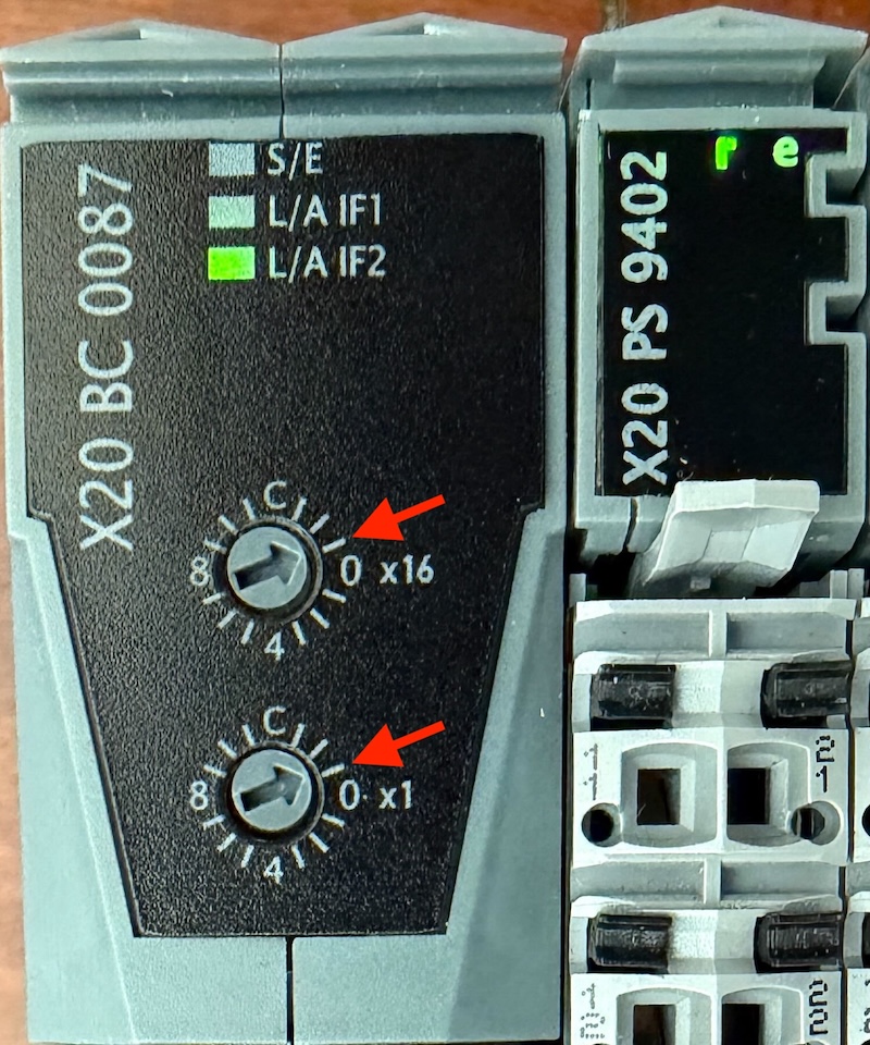
Connect the B&R X20 Bus Controller to your device using either port. Ensure your device’s Ethernet port is set to the same subnet as the B&R X20 Bus Controller. When using the default configuration, we recommend statically setting your device’s IP address to |
3. Dynamic Topologies
Defining Hardware as Code shines in real-world scenarios, such as managing different machine variants from a single codebase.
Because AddModule bindings are executed at runtime, you can use standard C++ control flow to alter your hardware footprint dynamically:
// If this is the "Premium" machine variant, initialize a second output module and map it.
if (machine_variant == "PREMIUM_MODEL") {
    // Binds to the second X20DO8322 module on the physical bus
    const auto premium_digital_out = io_driver->AddModule<X20DO8322>();
    premium_digital_out->DO1 << main_task->aux_heater_active;
}
4. Simulation & Unit Testing
Because Adapnex logic is native C++, this entire modular-I/O application can be simulated and tested exactly like our fixed-I/O applications. You don’t need a physical X20 bus controller on your desk to verify your thermostat logic.
For a deep dive into simulation and unit testing with Adapnex, refer to the Getting Started Guide.
5. Advanced Configuration
While the standard initialization uses sensible defaults, the B&R X20 driver is highly configurable for complex setups.
Customizing the Bus Controller
You can override the default IP address and cycle times by adjusting the network address switches and passing matching arguments to the driver. Changing the IP address is particularly useful if you need to connect and orchestrate multiple bus controllers on the same machine network.
// Custom IP (192.168.100.1) and custom cycle time (500us)
const auto io_driver = main_group->CreateTask<X20BC0087Driver>(
    std::array<uint8_t, 4>{192, 168, 100, 1},
    500us
);
Module-Specific Configuration
Many advanced slice modules allow programmatic configuration during initialization. For example, you can configure the specific sensor type of a thermocouple module directly in code:
// Configure the thermocouple module to use a Type J sensor
const auto temp_sensor = io_driver->AddModule<X20AT6402>(
    X20AT6402::SensorType::kTypeJ,
    16ms
);